Contents
- Learning Objectives
- Lecture Video
- Memory Management Unit (MMU)
- The SV39 Translation System
- Step-by-step How To Translate
- Leaf
- Mapping Addresses
- Unmapping Addresses
- Manual Translation
- Page Faults
- Demand Paging
Learning Objectives
- Understand how the SV39 MMU translates virtual addresses into physical addresses.
- Understand the procedure to map a virtual address to a physical address.
- Be able to map a virtual address to a physical address in code.
- Be able to unmap a given virtual address.
- Understand and be able to use sfence.vma.
Video
Memory Management Unit
The memory management unit translates virtual memory addresses into physical memory addresses. The memory management unit has one fixed location, which is typically a control register. This points the MMU to page tables which are located somewhere in RAM. By dissecting the virtual memory address, the memory management unit will dereference certain entries inside of the page table.
The SV39 Translation System
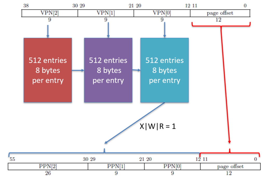
The RISC-V SV39 translation system uses 39-bit virtual memory addresses and up to three levels of page tables to translate virtual addresses into physical addresses. Each page table contains exactly 512, 8-byte entries, which is in total 4,096 bytes. This is convenient since this is exactly the size of a page.
Supervisor Address Translation and Protection Register

This is the register that the MMU will consult to find the page tables. The MODE field is either 0 (off) or 8 (SV39). The operating system will write which mode it wants into this field. The ASID field is the address space identifier. The ASID is used to speed up the TLB. In many cases, we have to flush the TLB every time the register is updated, otherwise we could translate a virtual address to an old physical address. The ASID is tagged on the TLB entry so that we can have the same address in the TLB multiple times, as long as the ASID is different. In our OS, we will use ASID = 0xffff (65535) for the operating system, and then set the ASID = lower 16 bits of a process id (PID).
The PPN field is the physical page number. We take a 56-bit physical memory location of the level 2 page table, and we shift it right 12 places, to make a 44-bit physical memory location. This location will then get stored in the PPN. We can shift the table right 12 places since page tables are at a memory location aligned at a 4KB boundary (\(2^{12}=4,096\)).
Virtual Addresses
A virtual address is 39-bits and is split into four parts: VPN2, VPN1, VPN0, and the page offset.

Physical Addresses
Physical addresses are the output of the memory management unit. For the SV39 system, a 39-bit virtual address inputs and a 56-bit physical address outputs. The physical address is shown below.

Page Table Entries
Each page table contains 512 total entries. These entries show the MMU where to go next to continue the translation. The entry has the following fields.

There are 512 entries per table, and 8 bytes per entry, for a total of 4,096 bytes per table.
The Valid Bit
The page table entry has several fields. The first field is the V bit, which means valid. We are not required to fill out every entry, and in fact, we don’t. Instead, we zero out the memory and only use the entries that we want to translate. The first thing we do is set the valid bit to 1 to tell the MMU that we know the entry is valid and we have set the fields accordingly.
The XWR Permissions
The next field is the permission bits: XWR. If the bit is set to 1, then the according permission is allowed, otherwise it is denied. For example, if X is 0, then the memory address translated CAN NOT be used in the instruction fetch cycle. The following table summarizes the permission bits.
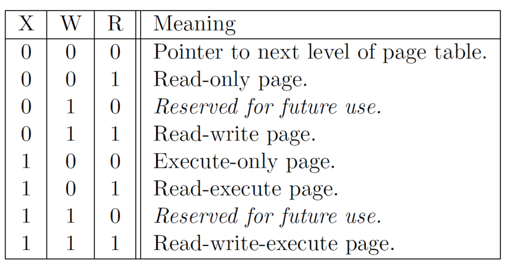
You will notice that if X, W, and R are all 0, then the page table entry describes a pointer (memory address) to the next level page table. This is known as a branch entry, since the tree branches out to the next level. Otherwise, this is known as a leaf entry, since if X, W, and/or R are 1, then the page table entry describes the physical address that the virtual address translated into.
The User Pages
The U bit stands for user, which means that it is a user page. In this case, mode 0 (user mode) can translate these addresses. If the U bit is set to 0 and a user mode process tries to translate the address, it is met with a page fault. NOTE: Older versions of the RISC-V standards allowed machine and supervisor modes to access user pages. This is no longer the case. Some architectures may still choose to use the old way. If a page is marked with a U, then your operating system WILL NOT be able to access it! The best thing to do in this case is to use mmu_translate to translate it to a physical address.
The Global Bit
Recall that we have an address space identifier (ASID) in the SATP register. This allows the TLB to mark entries that belong to different address spaces. I usually put the PID of a process in the ASID so that when we invoke a context switch, we don’t have to flush the TLB. This is known as a tagged TLB.
If an entry is marked with as a global entry by setting G = 1, then it is mapped across all address space identifiers. This is usually only done for certain I/O and virtual, dynamic shared objects, such as gettimeofday().
The Accessed and Dirty Bits
To implement demand paging, there are two “statistics” bits, the accessed and dirty bits.
The accessed bit is automatically set to 1 in memory by the MMU whenever that page is accessed–either read from or written to.
The dirty bit is automatically set to 1 in memory by the MMU whenever that page is written to.
So, if I just read from a certain memory address, then A=1 and D=0. If I write to a certain memory address, then A=1 and D=1.
Translation Steps
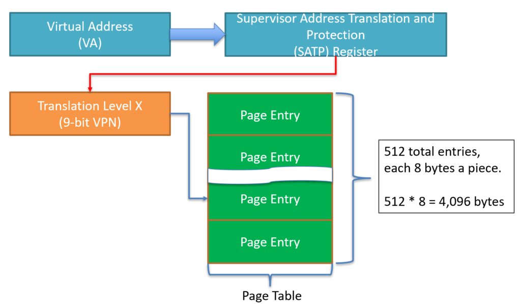
The MMU checks the SATP.mode register. If the mode is 0, the MMU is off, if it is 8, it is in the SV39 translation mode.
The rest of the steps assume the MMU is turned on.
- The MMU takes the \(\text{PPN}[55:0]=\text{PPN}[43:0]~\text{<<}~12\).
- The MMU goes to \(\text{PPN}[55:0]\) and adds \(\text{VPN}_2\times8\). We multiply 8 since each page table entry is exactly 8 bytes.
- The MMU dereferences \(\text{PPN}[55:0]+\text{VPN}_2\times~8\) and gets the level 2 page table entry.
- The MMU first checks the V (valid) bit. If this bit is 0, page fault. If this bit is 1, the MMU checks bits XWR (execute, write, and read).
- If X and W and R are all 0, this is a branch, meaning that PPN[2:0] will describe where the MMU can look for the next level page table. Otherwise, if X or W or R (or combination of) is 1, then this is a leaf.
Leaf at Any Level
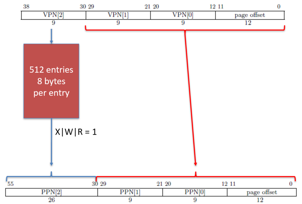
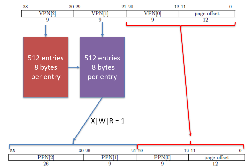
As you can see above, there can be a leaf at any level. This means we can have a leaf at level 2 (\(2^{30}=1\text{GB}\)), or level 1 (\(2^{21}=2\text{MB}\)), or level 0 (\(2^{12}=4\text{KB}\)), which is the most common.
What does it mean that we can have a gigabyte, 2 megabyte, or 4 kilobyte page? This means that when we translate, we translate everything but the last gigabyte, which is the last 30 bits, or 2 megabytes, which is the last 21 bits, or 4 kilobytes, which is the last 12 bits.
So, if we translate everything BUT the last 30, 21, or 12 bits, where do those bits come from? Well, the virtual address. The page offset is 12 bits for a level 0 leaf, 21 bits for a level 1 leaf, and 30 bits for a level 2 leaf. The following diagrams document how this functions. Essentially, the MMU is figuring out what parts to put together a physical address with–either the PPNs or the VPNs.
Leaf at Level 2
Leaf at Level 1
Leaf at Level 0
Mapping Addresses
Since we have a page allocator, and since every table must be page aligned, and since every table is the exact size of a page, we have an allocator that seemingly is specifically designed for our page tables! You would be correct. We will allocate pages using our page allocator.
To map an address, we walk the pages from the root to the leaf. Any time we reach an invalid page (PTE.V = 0), then we have to allocate another page to create a new table. Then, we update the page table entry to valid, and we point it to the freshly allocated (and zeroed) page.
SFENCE.VMA Instruction
The MMU is doing work even when it isn’t actively translating an address. It is permitted to speculate, meaning it can predict which addresses might be translated, and it will translate them when there is a lull in the action. The TLB speeds up MMU walks, so keeping it full of the most likely-to-be-translated addresses is the optimal plan.
Speculation leads to some synchronization problems. If an address is active in the TLB, the MMU will NOT walk the page table. So, if we modify a permission bit or something else that is in the page table entry, the MMU won’t see it. So, we must have a method to flush the TLB. This is where the SFENCE.VMA (supervisor FENCE: virtual memory address) instruction. This instruction has four forms.
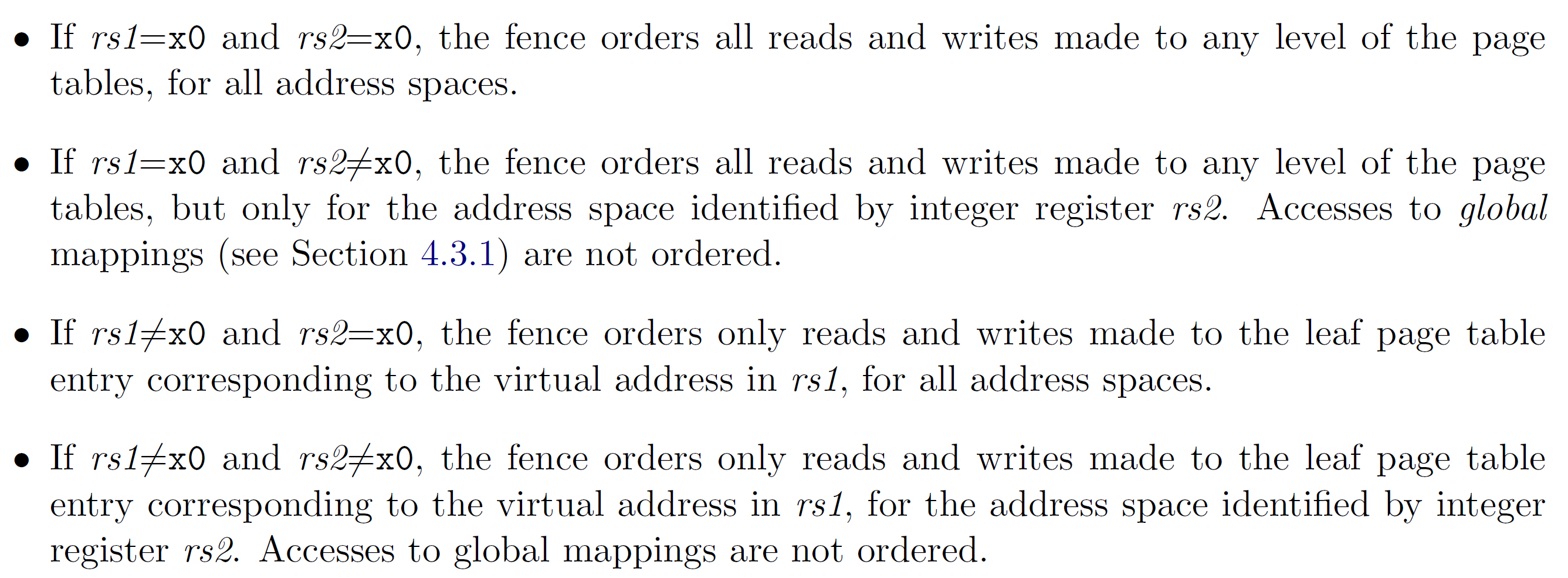
The SFENCE.VMA instruction takes two parameters: rs1 (the virtual address) and rs2 (the ASID). The x0 register mentioned in the graphic above is the zero register, which has a special meaning.
sfence.vma   zero, zero      # Flush ALL TLB entries
sfence.vma   zero, a0        # Flush TLB entries whose ASID matches the value of a0
sfence.vma   a0, zero        # Flush TLB entries whose virtual address matches the value of a0
sfence.vma   a0, a1          # Flush TLB entries that match the virtual address in a0 and ASID in a1
Using inline assembly, we can implement the following.
#define sfence() \
    asm volatile("sfence.vma zero, zero");

#define sfence_asid(asid)              \
    asm volatile("sfence.vma zero, %0" \
                 :                     \
                 : "r"(asid));

#define sfence_asid(asid, vaddr)       \
    asm volatile("sfence.vma %0, %1"   \
                 :                     \
                 : "r"(vaddr), "r"(asid));
An SFENCE.VMA should be executed in the following situations.
- When software recycles an ASID (i.e., reassociates it with a different page table), it should first change satp to point to the new page table using the recycled ASID, then execute SFENCE.VMA with rs1=x0 and rs2 set to the recycled ASID. Alternatively, software can execute the same SFENCE.VMA instruction while a different ASID is loaded into satp, provided the next time satp is loaded with the recycled ASID, it is simultaneously loaded with the new page table.
- If the implementation does not provide ASIDs, or software chooses to always use ASID 0, then after every satp write, software should execute SFENCE.VMA with rs1=x0. In the common case that no global translations have been modified, rs2 should be set to a register other than x0 but which contains the value zero, so that global translations are not flushed.
- If software modifies a non-leaf PTE, it should execute SFENCE.VMA with rs1=x0. If any PTE along the traversal path had its G bit set, rs2 must be x0; otherwise, rs2 should be set to the ASID for which the translation is being modified.
- If software modifies a leaf PTE, it should execute SFENCE.VMA with rs1 set to a virtual address within the page. If any PTE along the traversal path had its G bit set, rs2 must be x0; otherwise, rs2 should be set to the ASID for which the translation is being modified.
- For the special cases of increasing the permissions on a leaf PTE and changing an invalid PTE to a valid leaf, software may choose to execute the SFENCE.VMA lazily. After modifying the PTE but before executing SFENCE.VMA, either the new or old permissions will be used. In the latter case, a page fault exception might occur, at which point software should execute SFENCE.VMA in accordance with the previous bullet point.
Break Apart VPNs and PPNs
The first step is to break apart the virtual address into its components (VPNs and page offset) as well as the physical address.
unsigned long vpn[] = {
    (vaddr >> 12) & 0x1ff,
    (vaddr >> 21) & 0x1ff,
    (vaddr >> 30) & 0x1ff
};

unsigned long ppn[] = {
    (paddr >> 12) & 0x1ff,
    (paddr >> 21) & 0x1ff,
    (paddr >> 30) & 0x3ffffff
};
The starting point is the SATP register, so we need to check the root table and walk it until we hit a leaf. Recall that level 2 is the first level and level 0 is the lowest level, so we have to start at level 2.
We will need to identity map our kernel page table. An identity map is a mapping where the virtual and physical addresses are the same. There are a TON of addresses, so you will need to map at level 1 (2MB page) or level 2 (1GB page). You should map the heap using a 2MB or even a 1GB page to reduce the number of pages required to map all of the addresses.
Your MMU map should have a prototype similar to the following.
// Map one page (vaddr -> paddr)
bool mmu_map(PageTable *tab,  // root table
             uint64_t vaddr,  // virtual address
             uint64_t paddr,  // physical address
             uint8_t lvl,     // leaf level (2, 1, or 0)
             uint64_t bits    // entry bits
           );

// Map range of addresses (start_vaddr:end_vaddr -> paddr)
bool mmu_map_range(PageTable *tab,       // root table
                   uint64_t start_vaddr, // start virtual address
                   uint64_t end_vaddr,   // end virtual address
                   uint64_t paddr,       // start physical address
                   uint8_t lvl,          // leaf level (2, 1, or 0)
                   uint64_t bits         // entry bits
                 );
The function above takes a root page table (*tab), a virtual address and a physical address (the mapping), the level to make a leaf, which should be 0 (4KB page), 1 (2MB page), or 2 (1GB page). Finally, the bits are the bits you want the leaf to have, such as X, W, R, U, G, and so forth. You should always set the V (valid) bit regardless of the bits set.
Unmapping an Entry
When we unmap a table, we recursively clear every table that was created. So, we have to go through every entry and drill down all the way to a leaf. Recall that for each table, there are 512 entries. You need to check the V (valid) bit, which is bit at index 0.
We provide it with any table, and it will keep recursing any valid entry. It also needs to reset the entries to 0.
// Free a page table (from top to bottom)
void mmu_free(PageTable *tab);
Manual Translation
We will need to translate addresses manually in the kernel. Kernels will usually keep this as an internal table, but to learn the MMU and to learn how addresses are translated, we will manually translate by walking the page tables.
// Use the given page table to translate the
// virtual address to physical address.
// This will return -1UL for any page faults.
// -1UL is not a possible address, so it is safe
// to use it as a sentinel.
uint64_t mmu_translate(PageTable *tab,  // page table to walk for translating
                       uint64_t vaddr   // virtual address to translate
                       );
Manual translation will need to start at the root table (given by tab). Recall that there are 512 entries, and vpn[2] gives us the index to this root table. If at any time we get a page fault, we return -1UL. Since the maximum physical address size is 56 bits, -1UL is an acceptable sentinel value to denote a page fault.
Page Faults
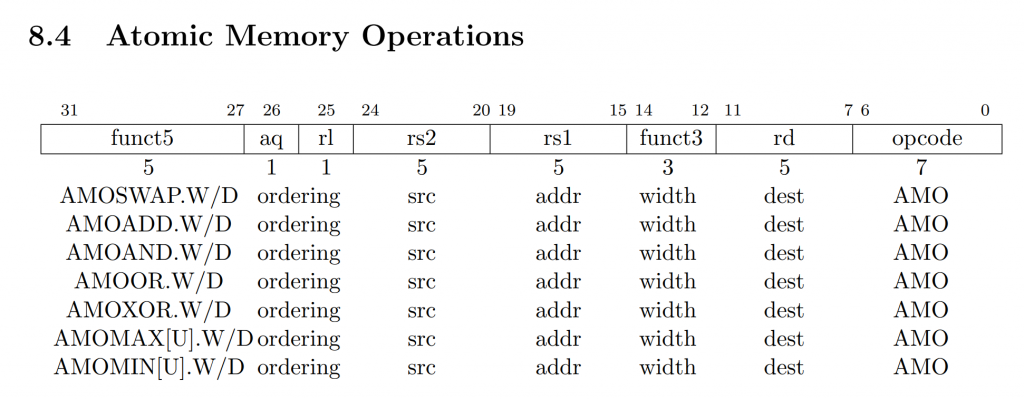
Page faults are notified through an exception, which is just an interrupt with a 0 at bit index 63. The following table shows that mcause=12 means an instruction page fault, mcause=13 means a load page fault, and mcause=15 means a store page fault. AMO stands for “atomic memory operation”, which we will use for locks.

Instruction Page Fault
An instruction page fault can be triggered for a number of things. (1) The memory address at the program counter (PC register) is not mapped. (2) The memory address at the program counter was not given read and execute permission, meaning the R and/or X bits in the page table entry are cleared to 0. (3) A user process is trying to access a non-user page, meaning the U bit in the page table entry is cleared to 0.
Load Page Fault
A load page fault can only be triggered on a load instruction (lb, lh, lw, ld). A load page fault can be triggered if the load memory address is not mapped, or it was not given read permission, meaning the R bit in the page table entry is cleared to 0. It can also be triggered if a user process tries to read from a non-user page, meaning the U bit in the page table entry is cleared to 0.
Store/AMO Page Fault
Just like a load page fault, a store page fault is triggered on a store instruction (sb, sh, sw, sd). A store page fault can be triggered if the store memory address is not mapped, or it was not given write permission, meaning the W bit in the page table entry is cleared to 0. It can also be triggered if a user process tries to write to a non-user page, meaning the U bit in the page table entry is cleared to 0.
Store/AMO page faults can also be triggered by an atomic memory instruction, such as amoswap and amoadd. These instructions will read and write to memory atomically. So, if the instruction is an AMO instruction, then it will always trigger a Store/AMO page fault.
Access Faults
There are other types of faults, called access faults. These are not triggered by the MMU, but can be triggered by the physical memory protection (PMP) system, or by the memory controller directly.
Demand Paging
As you see above, all page tables are store in RAM. When RAM is tight on a system, we can swap some of the pages out of RAM and onto a secondary storage system, such as a block drive.
The MMU is not in the loop with demand paging. This is purely an operating system technique, but we will use page faults to help us implement demand paging.
When we swap a page out of RAM and onto a disk, any accesses to that memory location will cause a page fault, since the branch leading to the swapped out page will not be valid. However, when our operating system handles the page fault, we don’t instantly determine it is an error. Instead, we have to search the page table map to see if we swapped it to the disk. If we did, we swap it from the disk back to RAM, and then we execute an sret (exception return). This will restart the offending instruction (usually a load or store or instruction fetch), and the underlying process will be none-the-wiser.
The SATP register is immediate. As soon as we set MODE=8, any memory transaction (read, write, or execute) will now go through the MMU. This includes the instruction fetch cycle! Things will come to a halt if they are not mapped correctly at this point.
Lastly, any entry in the TLB will be translated first, so any speculation must be flushed with SFENCE.VMA if any page table entry has changed.