Learning Objectives
- Understand the Sv39 MMU structure.
- Be able to identify the components of a virtual memory address.
- Be able to identify the components of a physical memory address.
- Understand what a page table is and what is contained within it.
- Identify and understand what each bit of a page table entry means and where it is located.
- Understand where page tables are located.
- Be able to translate a virtual memory address into a physical memory address.
- Understand where the MMU starts when translating a virtual address.
- Understand how a translation-lookaside buffer (TLB) speeds up translations.
Virtual Memory
We’ve been lying to you this whole time. Whenever you load and store from and to a memory location, the memory location isn’t real! These memory locations are called virtual memory locations, which get translated into a physical memory location using a logic device called the memory management unit (MMU).
The operating system is responsible for programming the MMU. Luckily for you, I won’t make you do this until you sign up for my operating system’s course. We just want to know the basics. However, I will have you pretend to be the MMU and translate a virtual memory address into a physical memory address. Each architecture has its own MMU scheme. For this lecture, we will be using the RISC-V architecture’s SV39 (39-bit virtual address) scheme. This scheme translates a 39-bit virtual address into a 56-bit physical address.
The Memory Management Unit
The memory addresses we load from and store to are virtual memory addresses. A virtual memory address has nothing to do with where a value is located in physical memory. Instead, the virtual memory address contains indices which tells the MMU where to look when translating the address into a physical memory address. The RISC-V Sv39 scheme splits a virtual memory address into the following fields.
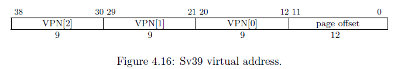
Notice we have VPN[2], VPN[1], and VPN[0]. VPN stands for virtual page number. The value (2, 1, and 0) refers to level 2, level 1, and level 0. Yes, we have a maximum of three levels of page tables. These are indices into an array that stores 512-entries. This is why we have 9 bits: \(2^9=512\). When the MMU is finished, it produces a physical address that looks as follows.
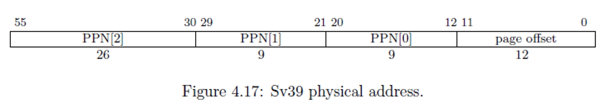
The physical address, when spliced together, is the actual location in RAM where we look for a value.
To get from the virtual address to the physical address, we use the memory management unit (MMU). The memory management unit uses the following flowchart to translate:

Page Tables
The memory management unit starts to translate by using page tables. These tables contain 512 page table entries. Each entry has the following format (remember, there are 512 of these).

Each page table entry is 8 bytes (64 bits), so \(512\times 8=4096\). Each table is exactly 4,096 bytes (4KiB). This size will come up a lot in the MMU, so don’t confuse them!
There are several bits here, including V, R, W, X, and so forth. The table below describes for what each bit is used.
| Bit(s) | Description |
|---|---|
| V | Valid bit. If this is 0, then the entire entry is invalid. This will cause the MMU to throw a page fault. |
| R | Read bit. If this bit is 1, then we are permitted to read from this memory address. Otherwise, the MMU will cause a page fault on loads. |
| W | Write bit. If this bit is 1, then we are permitted to write to this memory address. Otherwise, the MMU will cause a page fault on stores. |
| X | Execute bit. If this bit is 1, then the CPU is permitted to execute an instruction fetch (IF) at this memory address. Otherwise, the MMU will cause a page fault on IF. |
| U | User bit. If this bit is 1, then a user-application is permitted to RWX (depending on the bits above) at this memory location. If this bit is 0, the only the operating system can RWX at this memory location. |
| G | Global bit. This memory address is used for more than one application, so this is a hint to the cache policy. In other words, don’t evict it when we switch programs. |
| A | Accessed bit. Automatically set by the CPU whenever this memory address is accessed (IF, load, or store). |
| D | Dirty bit. Automatically set by the CPU whenever this memory address is written to (stores). |
| RSW | Reserved for Software. The operating system can put whatever it wants in here. |
| PPN[0..2] | Physical Page Numbers at levels 2, 1, and 0. |
| Reserved | Reserved for bigger entries (such as SV48 and SV56). |
PPN is in different locations!
Notice that we have PPN[2], PPN[1], and PPN[0]. These correspond to the same names in the physical memory address. However, the confusing part is that in the page table entry PPN[0] is at bit 10, but in the physical address, PPN[0] starts at bit 12. This means that they don’t line up exactly, so there is some shifting that you must do before you form the physical address.
These page tables are located in RAM. However, notice that only bits 12 through 55 contribute to the page table’s location in RAM. This means that the last three hex digits of where the table is located must be 0s. Therefore, 0xabcd_ef01 is NOT an appropriate memory address, but 0xabcd_e000 is. Recall that each hex digit is 4 bits, so \(4\times 3=12\). Funny enough, \(2^{12}=4096\). I told you this number would come up over and over again!
Supervisor Address Translation and Protection Register (SATP)
The MMU has a known starting point. This is a register called the supervisor address translation and protection (SATP) register. Since page tables can be located anywhere in RAM (given the last three hex digits are 0), the MMU has to have a defined starting point, and the SATP register is it!
The SATP register contains three fields and is described below.
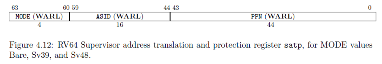
The three fields are: (1) mode, (2) address space identifier (ASID), and (3) physical page number (PPN).
The MODE Field
Only the operating system is permitted to write to this register. The MODE field determines if the MMU is turned on or off. If the MMU is turned on, the MODE determines what scheme the MMU will use. Here are the different modes.
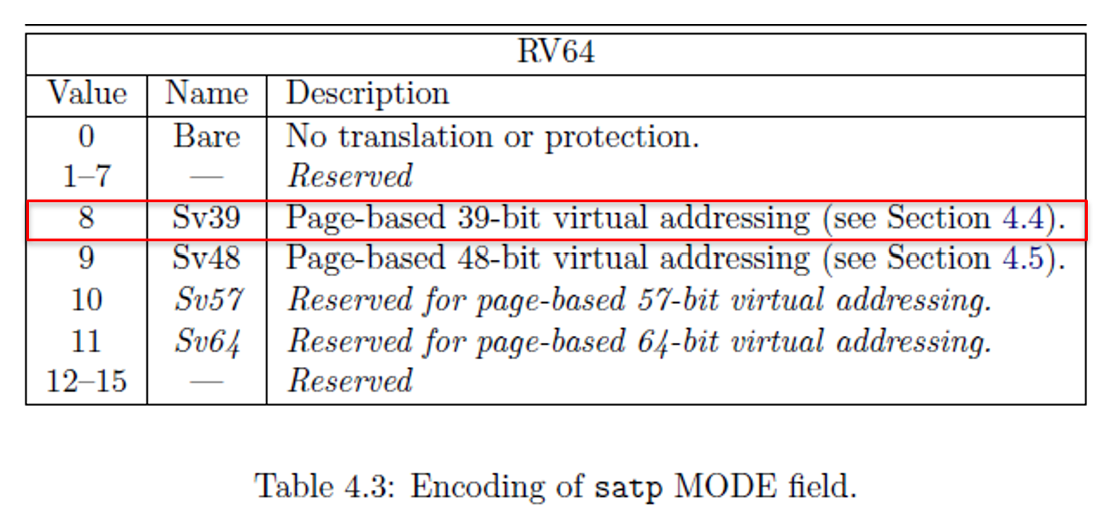
You can see that if the operating system sets the MODE field (upper four bits of the SATP register) to 0, the MMU is turned off. Otherwise, if the operating system sets it to 8, then the MMU will use the Sv39. This is a specification, and not all MMUs support all modes.
The ASID Field
The address space identifier (ASID) is used to tag the translation look-aside buffer (TLB) entries. The TLB is described more below, but the reason we do this is because every time we change the SATP register, we don’t want to flush out the cache (TLB). The operating system, instead, can put a value in ASID so the MMU knows who is using the MMU. When the MMU searches the TLB, it only matches those who match the ASID. Everyone else is ignored.
The Physical Page Number (PPN) Field
The physical page number (PPN) is where the first level (level 2) page table is located. Do NOT confuse this with PPN[2..0] in the page table entry, this is NOT the same thing. Instead, this is a physical memory address where the first page table can be located. However, notice that the PPN only stores 44 bits. Recall that the last 12 bits (last 3 hex digits) must be 0. So, instead of wasting space in the register to store these 12 0s, we store the physical address without these 0s. So, when we store the physical address of level 2’s page table, we first shift the address right by 12 places.
When the MMU wants to find the level 2 page table, it will take the PPN and shift it left by 12 places (adding 3 hex 0s to the right of the address), which makes a 56-bit address. Recall that all physical addresses in the Sv39 scheme are 56 bits.
Virtual Page Numbers (VPN)
The MMU has tables that contain 512 page table entries (PTEs). So, when we get VPN[2], that’s just an index into the level 2’s page table. Recall that each entry is exactly 8 bytes, so the MMU will first go to the SATP and grab PPN. It then shifts this PPN left by 12 places and adds VPN[2] times 8. Then, we can dereference this memory address and grab an 8-byte PTE.
$$PTE_{2}=(PPN_{\text{SATP}}<<12)+VPN_2\times8$$
In other words, to get a single entry from the 512 entries at level 2, we take the PPN from the SATP register, shift it left by 12 places, then add VPN[2] times 8. We multiply VPN[2] by 8 because each PTE is exactly 8 bytes.
Decoding the Page Table Entry (PTE)
When we dereference the memory address above, we get an 8-byte PTE. The MMU will first check the V (valid) bit. If this bit is 0, then the MMU can’t continue translating, and it will tell the CPU that the load/store/IF caused a page fault. Typically, your user application will print “Segmentation fault” and your application will crash whenever the MMU signals a page fault.
After checking the V bit, the MMU will check the RWX bits. If all three of R, W, X are 0s, then this entry is called a branch. The following chart describes what each RWX means.
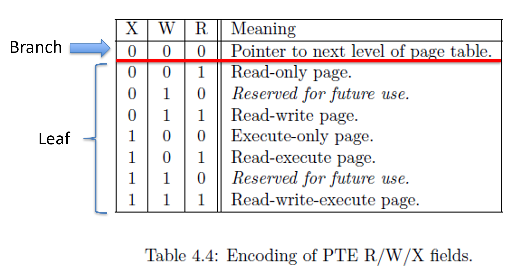
A branch means that we have yet another level of page tables to continue translation. A branch’s PPNs describe where to find the next page table (much like PPN in the SATP register). A leaf means that the page table entry contains the physical address to translate into.
Decoding Branches
Recall that a branch has the RWX bits set to 0. Then, we take PPN[2..0] and shift them into the physical memory address’ correct locations (bits 55 through 12). Notice that in the PTE it uses bits 53 through 10, so some shifting is in order! Whenever we form this new physical address, this is where in RAM the next level’s (level 1) page table is located. Whenever we get this memory address, we then take \(\text{PTE}_1=(PPN_2 << 30 | PPN_1 << 21 | PPN_0 << 12)+VPN_1\times 8\).
When we dereference this formed memory address, we will have \(\text{PTE}\) at level 1. Again, we look at the V (valid) bit, then the RWX bits, and do the same thing over and over again. If this is a branch, we have YET ANOTHER page table. Yes, there are a maximum of three page tables.
Decoding Leaves
Recall that we can have a leaf at level 2, level 1, and level 0. We can detect a leaf if RWX or any combination thereof are 1. When we have a leaf, we have to copy some portions of the PTE and some portions of the virtual address to form the final physical address. Each level determines how much comes from the virtual address and how much comes from the PTE to form the physical address.
| Level | PPN[2] | PPN[1] | PPN[0] | Page Offset (PO) | Resolution |
|---|---|---|---|---|---|
| 2 | PTE | VA | VA | VA | 1GiB |
| 1 | PTE | PTE | VA | VA | 2MiB |
| 0 | PTE | PTE | PTE | VA | 4KiB |
If we have a leaf at level 2, then only PPN[2] comes from the page table entry. We copy VPN[1] directly into PPN[1], VPN[0] directly into PPN[0], and the page offset becomes the last 12 bits of the physical address. However, if we have a leaf at level 1, then PPN[2] and PPN[1] come from the page table entry, where as VPN[0] copies into PPN[0] and PO copies into the page offset.
Having a leaf at level 2 means that the MMU only translates to the nearest gigabyte (1GiB). Everything else is copied directly from the virtual address. Having a leaf at level 1 means that the MMU only translates to the nearest 2 megabytes (2MiB). Everything else is copied directly from the virtual address. Finally, having a leaf at level 0 means that the MMU only translates to the nearest 4 kilobytes (4KiB). The page offset (last 12 bits) are copied directly to the physical address.
Address Resolution
If we have a leaf at level 2, then that entire 1GiB range will have the exact same read, write, execute, and user permissions. We don’t often see 1GiB page entries because this wastes a lot of space.
If we have a leaf at level 1, then the entire 2MiB address range will have the exact same read, write, execute, and user permissions. As with the 1GiB, the 2MiB page entries also waste quite a bit of space and aren’t widely used.
If we have a leaf at level 0, then the entire 4KiB address range (0xyyyyy000 through 0xyyyyyfff) will have the same read, write, execute, and user permissions. A 4KiB page is the most common page resolution. Recall that we can still narrow down to one byte by copying the page offset from the virtual address directly into the physical address.
Translation Look-aside Buffer (TLB)
The TLB is just a small piece of memory that keeps track of the most recent translations. Notice that when we use a pen and paper, it takes us a while to translate a virtual memory address into a physical address. The MMU takes quite a bit of time too (relatively). The TLB stores a virtual address and a physical address. So, when translating a virtual address, the MMU can look in the TLB first. If the virtual address is in the TLB, then it’s a direct lookup to get the physical address. If the virtual address IS NOT in the TLB, then we have to walk the page tables.
Practice
I wrote an MMU simulator for practice. Head on over to: https://web.eecs.utk.edu/~smarz1/courses/cosc130/mmu.
At the top, enter the problem ID 1.
You can type a memory address or SATP to dereference that given memory address or SATP register.
We are the MMU for these problems. So, for problem ID 1, we will translate the virtual memory address 0xdeadbeef. This memory address is used quite a bit as a joke and used for debugging purposes, but it’ll serve our needs here.
- Get the value of the SATP register. Check the mode to see if the MMU is turned on. Then shift PPN left by 12 places.
- SATP is 0x8000000000123456
- MODE = 8 (Sv39)
- ASID = 0
- PPN = 0x123456000
- Decompose the virtual address into VPN[2], VPN[1], VPN[0], and PO.
- 0xdeadbeef decomposes into {3, 245, 219, 0xeef}
- VPN[2] = VADDR[38:30]
- VPN[1] = VADDR[29:21]
- VPN[0] = VADDR[20:12]
- PO = VADDR[11:0]
- Add \(3\times 8=24=18_{16}\) to PPN (0x123456018)
- Dereference 0x123456018 to get PTE at level 2.
- This gives us 0x0000000000774101
- Check to see if it is valid (V bit = 1). Ours is 1, so it is valid.
- Check if this is a leaf or a branch.
- Our R, W, and X bits are all 0, this is a branch.
- Grab PPN[2], PPN[1], PPN[0] shift them into the correct location.
- Add \(\text{PTE}_1=\text{PPN}_1+\text{VPN}_1\times 8\)
- 0x774000 << 2 = 0x1dd0000 + VPN[1] x 8 = 0x1dd07a8
- Dereference 0x1dd07a8 to get PTE at level 1.
- This gives us 0x0000000000002001
- Again, check the valid and RWX bits. Ours is valid and is yet another branch (RWX all equal 0).
- Dissect PPN[2]:PPN[1]:PPN[0] which is 0x2000 << 2 = 0x8000 + VPN[0] x 8 = 0x86d8.
- Recall we have to shift left by two places since in the PTE PPN[0] starts at bit 10 and in the physical address, it starts at bit 12.
- Dereference 0x86d8 to get PTE at level 0.
- This gives us 0x000000000001700f
- Yet again, check the valid and RWX bits. Ours is valid and RWX are all set, this is a leaf. IF this was a branch, there are no more levels, and the MMU would page fault.
- Shift PPN[2], PPN[1], and PPN[0] into place and copy the page offset from the virtual address (0xeef).
- Remember, a leaf at level 2 only uses PPN[2] here, everything else is copied from the virtual address.
- Remember, a leaf at level 1 only uses PPN[2] and PPN[1] here, everything else is copied from the virtual address.
- 0x17000 << 2 = 0x5c000 + PO = 0x5ceef.
- Therefore, 0xdeadbeef (virtual) translates into 0x5ceef (physical).
Conclusion
The MMU can be a complicated piece of equipment. It will take practice to get all of the rules in place, checking the valid, checking RWX, and knowing what portions come from the PTE and which come from the virtual address.
You can see all of the steps to translating a single virtual address into a physical address. This is why a TLB is necessary, especially for those memory intensive applications. Without a TLB, every load, store, and instruction fetch would require us to translate using the steps above!
Keep at it. Practice will help!