Learning Objectives
- Be able to reduce a circuit equation using Boolean algebra and a k-map.
- Understand the rules to apply to a k-map when drawing loops.
- Distinguish between SOP and POS forms.
Motivation
Large circuit equations get quite cumbersome. Also, every term is another logic gate, whether that be a NOT, AND, or OR. Therefore, we want to make sure our little electrons have the best path to their destination. This reduces the amount of current necessary as well as reduces the amount of wasted energy. Most wasted energy is transformed into heat, so larger and more cumbersome circuits can generate a lot of heat.
There are two methods to reduce circuit equations: (1) Boolean algebra and (2) Karnaugh maps (k-maps). The goal of both methods is to remove as many gates as possible and still have an equivalent circuit. Take the following truth table and associated circuit equation.
| A | B | C | Q |
|---|---|---|---|
| 0 | 0 | 0 | 0 |
| 0 | 0 | 1 | 0 |
| 0 | 1 | 0 | 1 |
| 0 | 1 | 1 | 1 |
| 1 | 0 | 0 | 0 |
| 1 | 0 | 1 | 0 |
| 1 | 1 | 0 | 1 |
| 1 | 1 | 1 | 1 |
Using SOP, we get a circuit equation of \(Q=A’BC’+A’BC+ABC’+ABC\). We can take a look at the truth table and realize that we only get a 1 when B is 1. Therefore, the only factor we care about is \(Q=B\). However, this might not be obvious, so we need a way to formally work our way through a circuit equation. This is where Boolean algebra and k-maps come into play.
Boolean Algebra
Boolean algebra uses algebra (go figure?) to reduce circuit equations. Our goal is to move terms around and get our equation into one of the following reductive states.
For example, \(Q=A + A’\). What this circuit equation is telling is that Q is going to be 1 if A is 1 or if A is 0. This means no matter what we put into A, Q will be 1. So, this can be reduced to \(Q=1\). In fact OR’ing a term with its complement is one of these reductive states.
Reductive States
$$Q=A+A’=1 \\ Q=A+A=A \\ Q=A+1=1 \\ Q=A+0 = A$$
$$Q=A\cdot A = A \\ Q=A\cdot A’=0 \\ Q=A\cdot 1=A \\ Q=A\cdot 0 = 0$$
We can move terms around since we’re only dealing with multiplication and addition. Both of these operations have the associative and commutative properties. Associative means that \((A+B)+C=A+(B+C)\), or that the ordering of parentheses doesn’t affect the outcome. Commutative means that \(A+B=B+A\), or that the ordering of terms doesn’t affect the outcome.
Recall that in math that \(x=a(b+c)=ab+ac\). This is the distributive property, and we can use it in Boolean algebra. There is even a distributive property you haven’t seen, which is \(Q=A+BC=(A+B)(A+C)\). The only reason this one works is because A, B, and C all have a co-domain of 1 and 0 (binary). Here are the distributive properties of Boolean algebra.
$$Q=(A+B)(C+D)=AC+AD+BC+BD (\text{F.O.I.L}) \\ Q=A(B+C)=AB+AC \\ Q=A + BC = (A+B)(A+C)$$
Recall that all of these are associative and commutative, so \(A+BC=BC+A=(A+B)(A+C)\).
To see why this holds true, let’s take \((A+B)(A+C)\) and see if we FOIL (first, outer, inner, last) it, what we get:
$$(A+B)(A+C)=AA+AC+BA+BC=A(1+C+B) + BC=A+BC$$
Recall that anything OR’d with 1 is 1, so \(1+C+B=1\). We can use substitution to make this even clearer. Let \(S=C+B\), so \(1+S=1\).
This is more-or-less how we reduce equations using Boolean algebra. Unfortunately, some trial-and-error is required to see what we get. Let’s take our original equation to see if we can get \(Q=B\).
$$Q=A’BC’+A’BC+ABC’+ABC \\ Q=A’B(C’ + C) + AB(C’ + C) \\ Q=A’B + AB \\ Q = B(A’ + A) = B(1) \\ Q = B$$
Just as we thought, Q is indeed equal to B. The first step is to look for like terms. The more we can factor out, the easier this will work for us. I noticed A’B was common between two terms and so was AB. So, we factor those out to leave \(C+C’\), which anything OR’d with its complement is 1. So, we get 1. Then I noticed that B was a common factor between \(A’B\) and \(AB\). So, we factor those out and yet again we get A OR’d with its complement. This leaves us with just B.
Adding Terms to Reduce Them
Sometimes it takes a counter-intuitive approach to reduce an equation. Sometimes we need to actually add terms to reduce an equation. Take the following equation, for example: \(Q=AB’C’+AB+A’BC\) In this equation we see we actually have three inputs, A, B, and C, but that middle term lacks a C. If we try to reduce this equation, we don’t get very far. So, let’s add a C back into the middle term: \(AB=ABC+ABC’\). That’s right, we added two terms to replace one. This doesn’t change the outcome of the equation because \(ABC+ABC’=AB(C+C’)=AB\).
Now, let’s see how we can reduce this equation.
$$Q=AB’C’+ABC+ABC’+A’BC \\ Q=AC'(B’+B)+BC(A’+A) \\ Q=AC’ + BC$$
Example: Reduce \(Q = A’B’C’ + A’B’C + A’BC’ + A’BC + AB’C’ + AB’C + ABC’ + ABC\)
$$Q = A’B’C’ + A’B’C + A’BC’ + A’BC + AB’C’ + AB’C + ABC’ + ABC \\ Q = A’B'(C’ + C) + A’B(C’ + C) + AB'(C’ + C) + AB(C’ + C) \\ Q = A’B’ + A’B + AB’ + AB \\ Q = A'(B’ + B) + A(B’ + B) \\ Q = A’ + A \\ Q = 1$$
We can see that indeed, we have 8 terms. That means that ALL rows of the truth table had an output of 1, so no matter what we did with the inputs, we get 1.
Karnaugh Maps
Karnaugh maps (or k-maps) are a visual way to perform Boolean algebra, and is the more preferred method. There are far fewer places to make mistakes, and k-maps don’t require trial-and-error like some Boolean algebra problems.
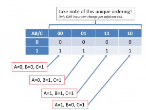
A k-map uses a table to show the different outputs and the inputs required to give the output. The table is laid out with the inputs on the outsides of each cell (square). The output is then put into the table’s cell. Below is an example of the following truth table.
| A | B | C | Q |
|---|---|---|---|
| 0 | 0 | 0 | 0 |
| 0 | 0 | 1 | 1 |
| 0 | 1 | 0 | 0 |
| 0 | 1 | 1 | 1 |
| 1 | 0 | 0 | 0 |
| 1 | 0 | 1 | 1 |
| 1 | 1 | 0 | 0 |
| 1 | 1 | 1 | 1 |
The k-map is in a table form, as shown above. When I write AB/C that means AB is OVER C. So as we move from the leftmost column, we have A=0,B=0, to the adjacent column, we have A=0,B=1. Notice the unique ordering of input values. For a k-map to work properly, only one input must change when we move adjacent cells. When we look at the rows, the top row is where C=0 and the bottom row is where C=1.
Now comes the reducing part. We draw what are called loops and apply the following rules. We can apply SOP or POS forms on a k-map. For SOP form, we’re looking to loop all of the 1s. In POS, we’re looking to loop all of the 0s. The more loops we have, the more terms our equation will have, so we’re looking to minimize loops. Here are the rules:
- Minimize the number of loops.
- Maximize the number of 1s (SOP) or 0s (POS) in a loop.
- The number of 1s (SOP) or 0s (POS) must be a power of 2: 1, 2, 4, 8, 16, etc.
- Always consider “wrapping” (top-to-bottom or left-to-right)
We need to double check that all 1s in SOP or all 0s in POS are encapsulated in some loop. We can’t leave any dangling 1s or 0s. Always consider the wrapping. Take a look at the leftmost and rightmost columns. Notice that only one input changes, so we need to consider the edges of k-maps too. This particular example doesn’t have any wraps, but always consider them!
So, we loop the entire bottom row. We’ve minimized the number of loops, maximized the number of 1s in the loop (for SOP), and made sure that we had a power of 2 (we have 4 1s). Then, we need to take a look at the loop and see what changes within the loop. If an input changes inside of a loop, that means the input did NOT have an impact on the output, and therefore, it can be eliminated.
Looking at the red loop, notice that we get a 1 as long as C=1 and regardless of what the values of A and B are. This means that within this loop, the inputs A and B are meaningless. Therefore, our circuit only relies on \(Q=C\).
Just like with a truth table, in SOP form, we add inputs in a loop using AND (\(\times\)) gates. We combine loops using OR (+) gates.
Example
Reduce the following circuit:
$$Q=A’BC’D’+ABC’D’+A’B’CD+A’BCD+ABCD+AB’CD+A’B’CD’+A’BCD’+ABCD’+AB’CD’$$
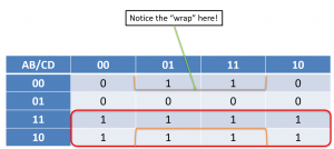
We first need to set up our k-map table. Since the circuit equation above is in SOP format, each term is where the k-map cell will be 1.
Now, we need to apply the rules and loop a maximum number of 1s (don’t forget powers of 2). Also, we need to consider wrapping!
If we did not consider the amber “wrapping”, we would have two loops of 2 1s. This violates the rules of “minimize loops” and “maximize the number of 1s in a loop”. Notice that only one input changes from the top row to the bottom (namely, the A input goes from 0 at the top to 1 at the bottom).
Now we need to analyze the loops to see what input changes. Recall that any input that changes within the loop is irrelevant and can be eliminated. Let’s take a look at the red loop first. We see that if we move down a row, the input D changes. As we move across each of the four columns, both A and B change. So, this one loop is \(Q=C\).
Let’s take a look at the amber loop. From the top row to the bottom row, the input C changes from 0 to 1. However, D remains constant. So, as long as \(D=0\), then this loop holds. Let’s analyze the columns. We’re stuck in the middle two columns. Between those two, the input A changes, but B remains constant at 1, so only the input B matters. That means as long a D=0 and B=1, then our output is also 1. Recall that we combine inputs using AND gates in SOP form and we combine loops using OR gates. So, our circuit equation becomes:
$$Q=C+\bar DB$$
Notice that we’ve eliminated an entire input. The input A doesn’t make any difference in this circuit equation. If we draw the circuit diagram, we’d get the following.


