Learning Objectives
- Be able to identify the each stage of the five-stage pipeline.
- Understand the benefits and problems with a pipelined CPU.
- Identify hazards given assembly code.
- Identify possible solutions to given hazards.
Pipelining
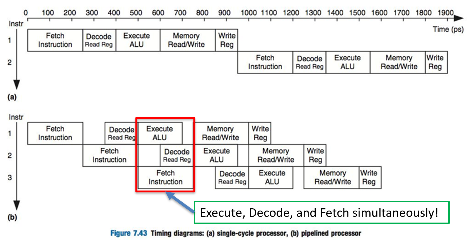
Pipelining allows functional units to operate simultaneously.
Stage 1: Instruction Fetch (IF)
The instruction fetch (IF) stage goes into memory and fetches the machine code (the 0s and 1s) that make up an instruction. The IF stage knows where to go to get the next instruction by using the program counter (PC). Which is a register that holds the currently executing instruction. The program counter automatically moves to the next instruction, or it can be set indirectly by branch and jump instructions.
Stage 2: Instruction Decode (ID)
The instruction decode (ID) stage decides what instruction is executing and decodes the values of the source registers or immediate. So, the registers must have their proper values at this stage.
Stage 3: Execute (EXE)
The execute (EXE) stage performs the binary arithmetic in either the arithmetic and logic unit (ALU) or the floating-point unit (FPU). This is where the majority of the “action” takes place. This stage then produces a final result.
Stage 4: Memory (MEM)
This stage is mainly for the load and store instructions. We decode the instruction in stage 2 (ID), calculate any offsets in stage 3 (EXE), and then actually go out to memory and make either a read (load) or write (store) request.
Stage 5: Write-back (WB)
The fifth and final stage writes the result into the destination register. This is applicable to all instructions, except the store instruction, where the destination would be written in stage 4. Notice that stage 2 is where we read the registers, but stage 5 is where we write to the destination register. This distance between stage 2 and stage 5 can cause what is known as a hazard.
Pipeline Hazards
Just like anything in life, we have to take the bad with the good. Pipelining ensures that we have all of our functional units at full capacity, however doing this can lead to some pretty harsh results. I hinted at one problem in the description to stage 5. However, what this is called is a read-after-write (RAW) hazard. There are three types of broad hazard categories: (1) data, (2) control, and (3) structural.
Data Hazards
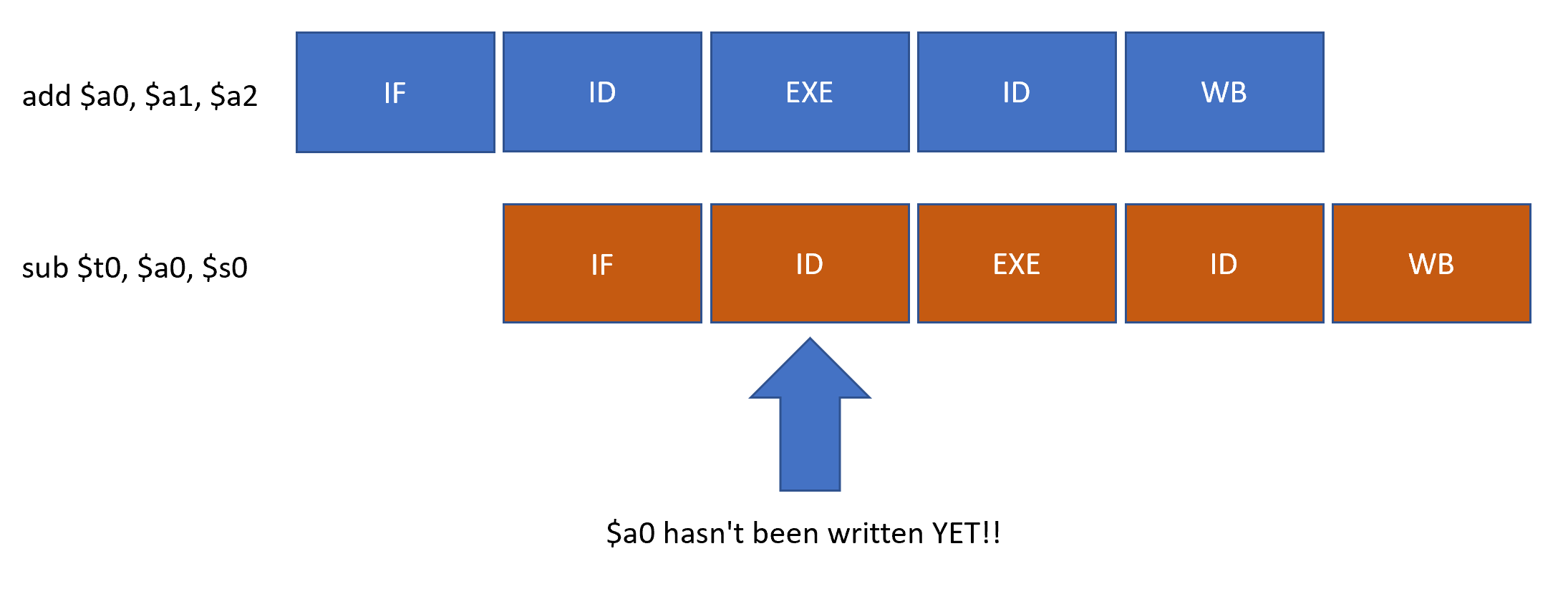
Let’s take the following example to see what can cause a RAW data hazard.
add $a0, $a1, $a2
sub $t0, $a0, $s0
In the assembly code above, we add a1 and a2 together and write the result into a0. However, look at the very next instruction, the sub instruction. We are using the result a0 as one of our source operands. Now consider that it is stage 2 where we get the values of the registers, but it’s stage 5 where the add instruction will write to $a0. Here’s a diagram depicting what’s happening.
The only data hazard that is directly attributable to pipelining is the read-after-write hazard. There are two more, but these are more about dependencies than a problem with pipelining. These are (1) write-after-read (WAR) and (2) write-after-write (WAW). Mainly, these are a problem when we try to reorder instructions–which we do to solve RAW hazards.
So, how do we solve the RAW hazard above? One way is to put other instructions in-between the add and sub instructions, but again, we need to make sure that the data dependencies make sense. We want to make sure that when we read from a register, it has the proper data in place.
As you can see above, we need to know the $a0 register’s value at the ID stage. However, if we can put three more instructions in-between the add and sub, then our ID stage for our sub instruction will come after the add’s writeback stage.
The problem with this is that there might not be any other instructions that we can arrange out of order.
One way to solve all hazards is called a stall (also known as a bubble). Essentially, we put instructions in-between the add and sub instructions that don’t do anything. This type of instruction is called a nop (no operation). In MIPS, there are several instructions that we can substitute for nop, such as addi $zero, $zero, 0. However, since we’re not doing any useful work, this ruins our performance.
A better way to solve the RAW hazard is to use operand forwarding. Notice that we actually know the result of $a1+$a2 in stage 3, the execute stage. So, why not forward the result from stage 3 to the sub instruction’s stage 2? This is exactly what happens in operand forwarding. A diagram of a forwarded operand is below.
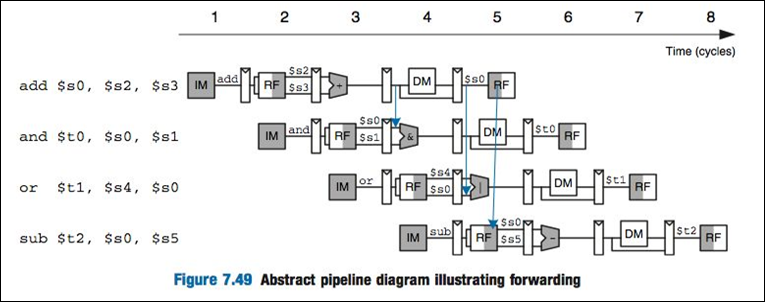
Notice the square boxes in-between each pipeline stage. These are intermediate registers and their job is to store the output of that pipeline’s stage. So, we can directly grab the output of the execute stage after the add instruction above. Notice the blue line forwards the output of the execute stage of the add instruction into the and instruction’s execute stage. This is an example of operand forwarding.
Control Hazard
Control hazards are also known as branch hazards. Notice that we fetch the next instruction while the first instruction is decoding its operands. What happens with a branch? We don’t really know what instruction is next until we solve the branch. For example, if we have bne $t0, $t1, here, do we load the instruction directly under the branch instruction or do we load the instruction pointed to by the label here?
This is an example of a control hazard. We have two mutually-exclusive instructions and only one needs to be loaded into the pipeline. If we choose the wrong instruction, we have to flush out the erroneous instruction and replace it with the new instruction. A pipeline flush can be accomplished by feeding 5 no-operations. This stalls the pipeline, and hence, it ruins our performance.
Another way to help, but not completely solve, control hazards is to add a logic unit called a branch predictor. These are logic units that store how many times we took the branch or did not take the branch. So, it uses history to predict what instruction should load into the pipeline. Obviously, since it has to predict the future, it will eventually be wrong, and we suffer the pipeline consequences. However, some branch predictors are quite clever and solve nearly 90% of control hazards!
Structural Hazard
A structural hazard occurs when two instructions require the same functional unit. This is usually not a problem with most CPUs. However, consider CPUs with multiple cores. There is only one bank of memory, so at stage 4, we have to prioritize and order reads and writes to memory. This can cause one core to stall while it waits for its turn.
Another way to solve a structural hazard is quite obvious–add more functional units. In fact, we have CPUs that do this. They are called superscalar machines because they have more (super) functional units (scalar). Machines that have only one functional unit per stage are called scalar machines. Machines that require one functional unit for multiple stages are called subscalar machines. We don’t see subscalar machines very often, and they tend to only occur in embedded systems.